


Search for ""
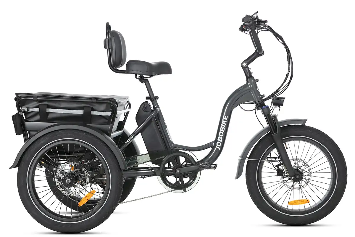
The basket can be installed on the front rack in Robin, Robin ST, Transer, Commuter, Linda, Lyon, Eddy, Eddy X, and installed on the rear rack in Robin, Robin ST, Transer, Commuter, Linda, Lyon, Eddy, Eddy X, Sam, Romer.
If you want to mount a basket on the front of your ebike, check our Accessories to find the Front Rack.
Watch the video and follow the steps below to install basket on your bike.
Step 1
Place the side of the basket with the fastener at a proper position on the rear rack, and then press the basket down, so that the basket is installed on the rear rack.
Step 2
Open the fastener at the bottom of the basket by hand, and the basket can be removed from the rear rack.
Step 3
We can install the basket on the front rack in the same way as we did the installation on the rear rack.

Check out the current list of Compatible Accessories for your JOBOBIKE Robin and Robin step-thru.
Need any help installing accessories? Visit the Overview of Accessories section of our Help Center.
Step 1 Before opening the box
Record the exclusive bike information on the side of the box with your phone. Make sure it is with the correct direction and without serious damage
Step 2 Unpack the E-bike
Open the package and take out all of the parts. Be careful not missing even a little piece of part.
The parts shall include:
| Front Wheel | Front Fender |
| Toolkits | Charger |
| Keys (2 identical) | Headlight |
| Quick Release | Pedals |
| E-bike Frame | Display |
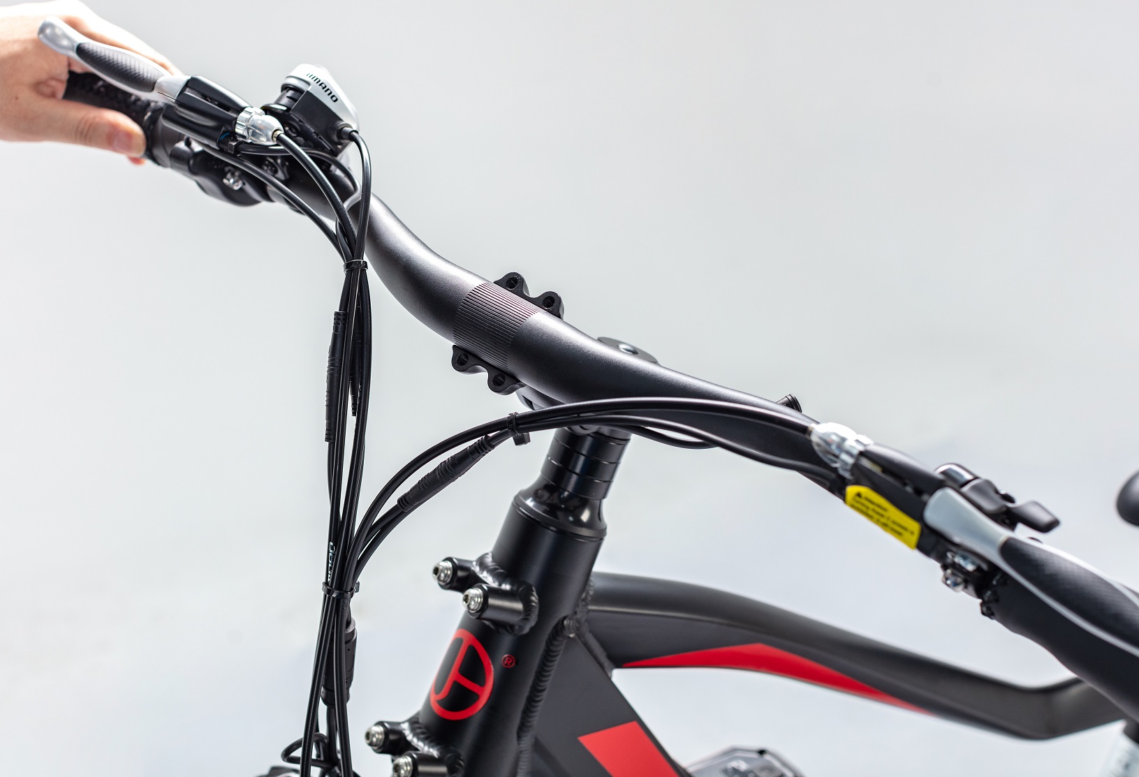
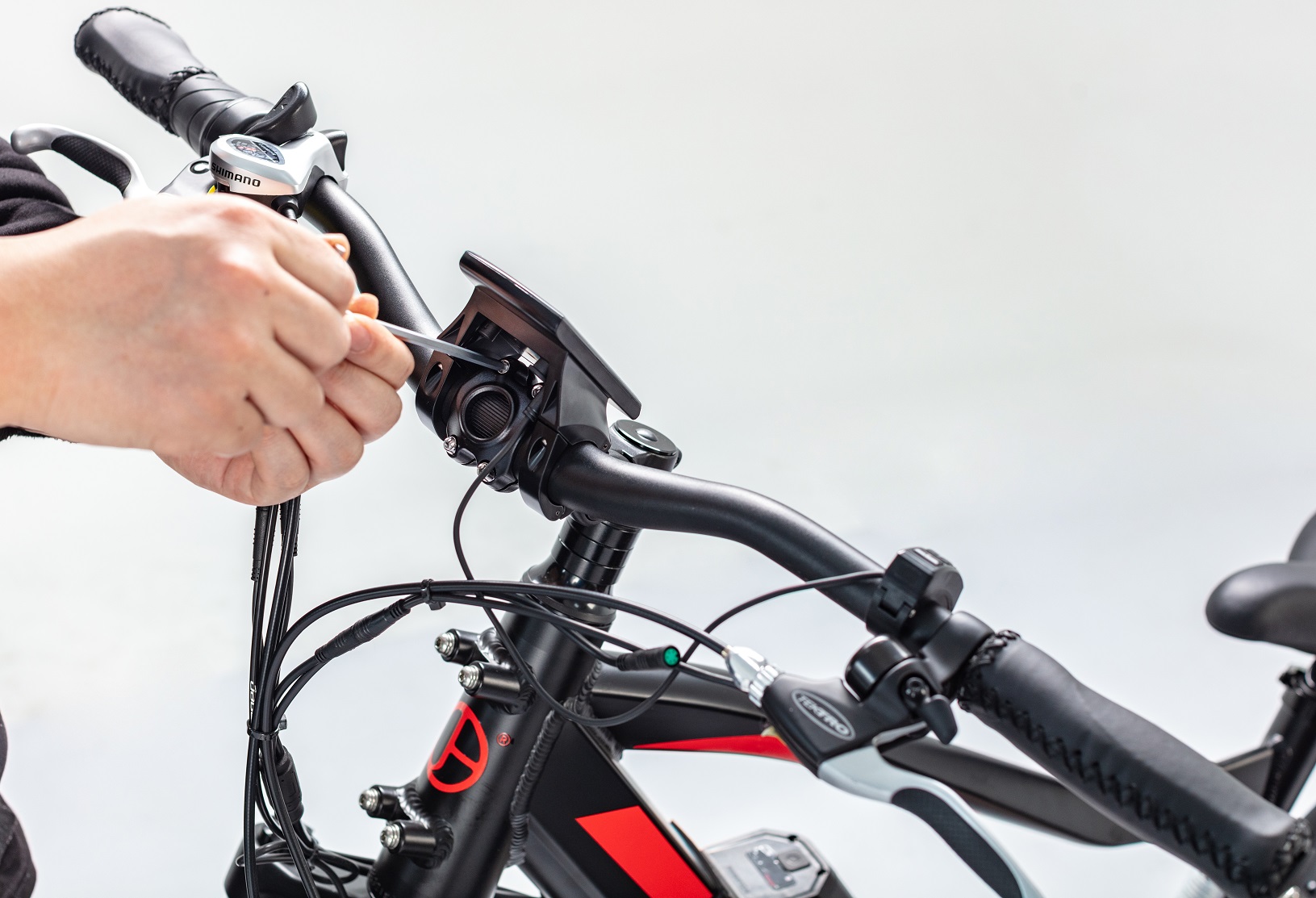
Step 3 Install the handlebar
Install the handlebar to the stem and fix it with matching screws by a 4# hexagon wrench. During installation, adjust the handlebar to an appropriate angle so that the electric bicycle can be operated comfortably. Make sure the four screws are tightened enough and the handlebar cannot be moved.
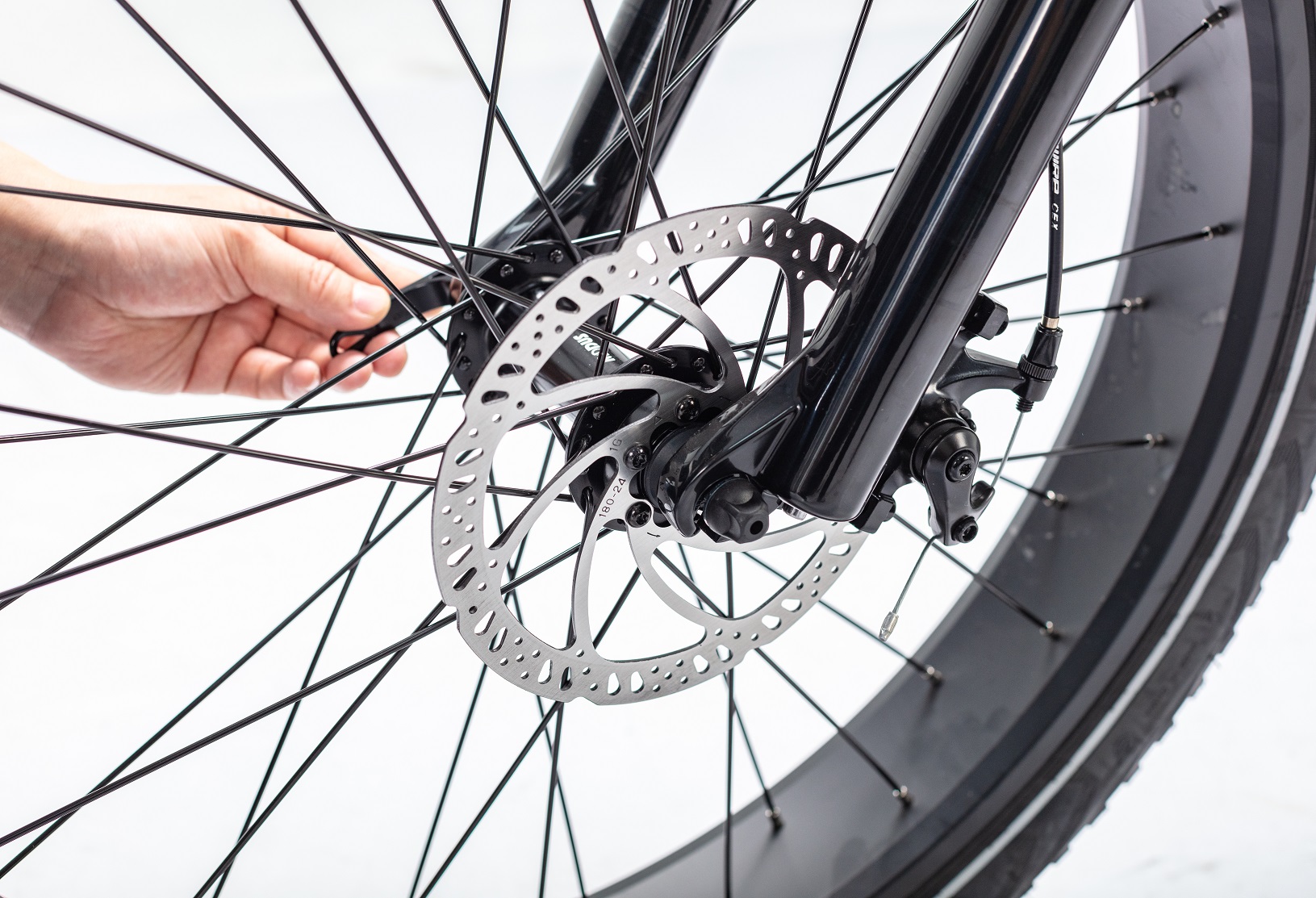
Step 4 Install the front wheel
4.1 Place the front wheel in the correct position of the fork groove and tighten it with matching quick release. (if there are any hub protection parts attached to the wheel, remove them)
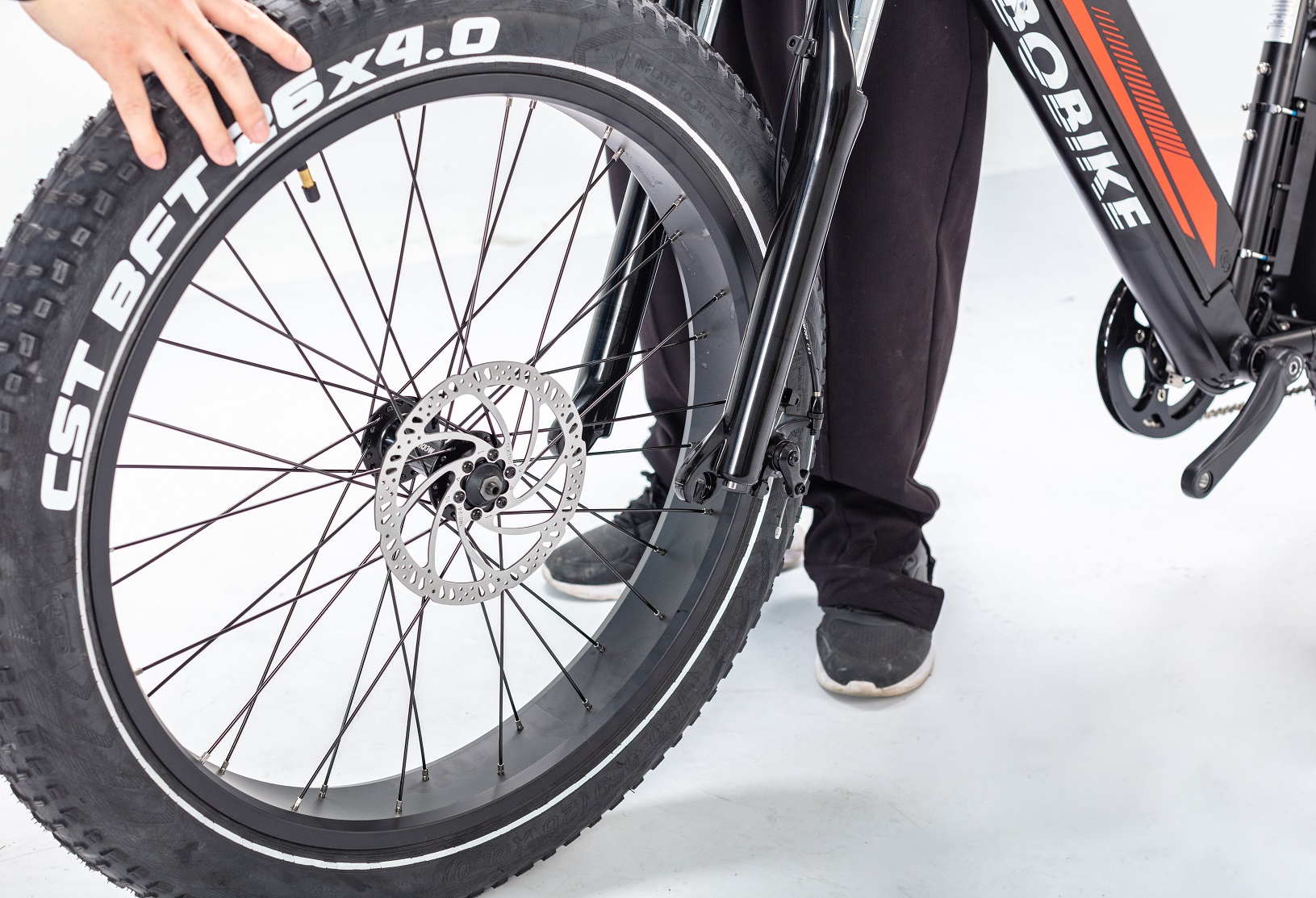
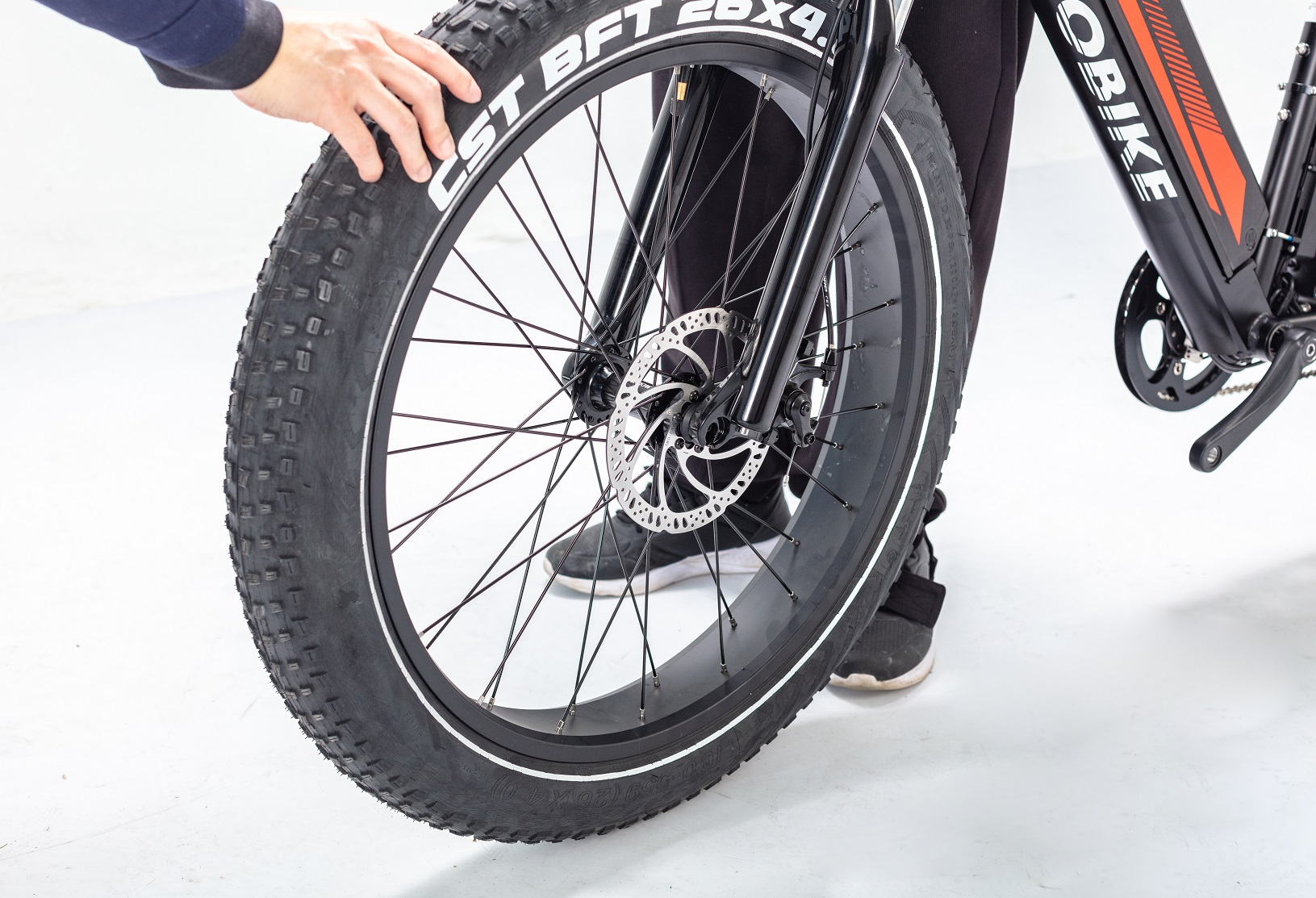
4.2 Make sure the front wheel will not rub the brake pads when it is rotating under the condition of not pinching brake handle.
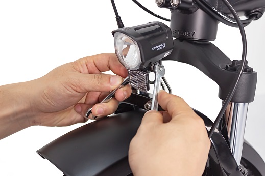
Step 5 Install the front fender and headlight
5.1 Install the front fender and headlight on the front fork with matching screws and nuts by a 4# hexagon wrench. Make sure the front fender and headlight support cannot be moved.
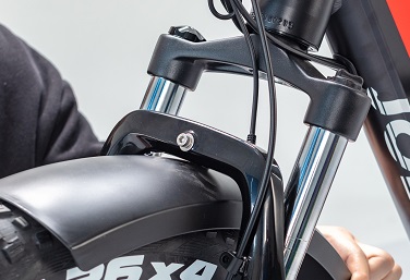
5.2 Adjust the headlight to a proper angle by this way: loosen the adjusting bolt with the 8# wrench, adjust the headlight tilt angle to the best position, and then tighten the bolt.
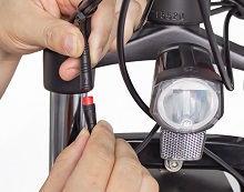
5.3 Connect the cable plug to the headlight, please note to align the inner pins and notches with the outer arrows.
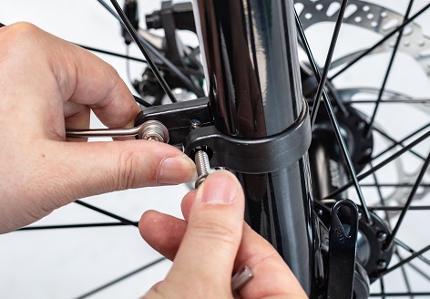
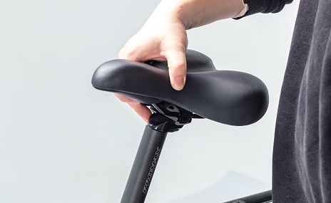
Step 6 Adjust the saddle height
Move the saddle up or down to your desired saddle height. Do not raise the saddle post exceeding the minimum insertion mark on the saddle post. Close the quick release lever and make sure the lever is tighten enough when locking the saddle post.
Step 7 Install the pedals
The “L” mark refers to the left pedal.
The “R” mark refers to the right pedal.
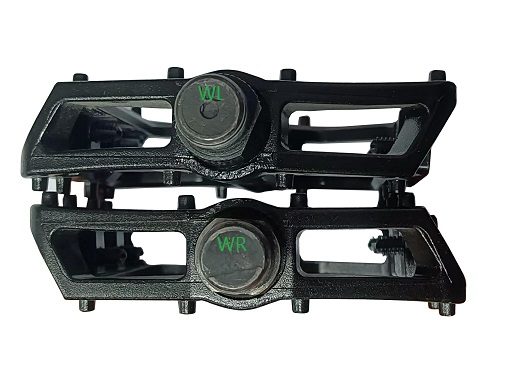
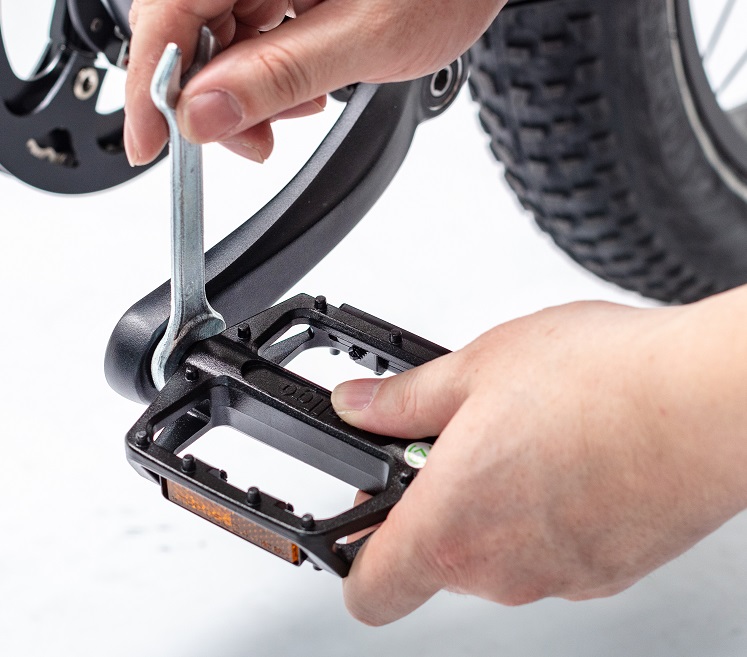
Tighten the right pedal clockwise and tighten the left peddal counterclockwise with the 15# wrench.
Note: Please carefully thread each pedal into it’s appropriate crankset.
Step 8 Inflate the tyres
Check whether the tyres beads and tyres are evenly seated on the rims. Use a pump with a Schrader valve and pressure gauge to the recommended pressure indicated on the tyre sidewall.
Note: Do not over inflate or under inflate tyres.
NOTICE: Both wheels must be properly settled before operating your bike. If you are not able to assembly your bike, please contact us or look for help from a certified, reputable local bike mechanic.Ensure all hardware is tightened properly.
Minors are prohibited from riding.
13.1 Symptom: The battery shell is damaged.
Solution: Please repair the shell if it can be properly repaired. If the damage is serious, replace the battery with a new one.
Applicable to 5S protocol:
| Error code | Robin | Eddy | Sam |
|---|---|---|---|
| Current abnormal 21 | Y | Y | Y |
| Throttle abnormal 22 | Y | Y | Y |
| Phase abnormal 23 | Y | Y | Y |
| Hall sensor abnormal 24 | Y | Y | Y |
| Brake abnormal 25 | Y | Y | Y |
| Communication abnormal 30 | Y | Y | Y |
| MOSFET damage 31 | Y | Y | |
| Key stickness 32 | Y | ||
| Key stickness 33 | Y | ||
| Note: Y stands for YES |
Definition of error code of Bafang central system:
| Error code | Bruno | Henry | Linda/Lyon |
|---|---|---|---|
| Overvoltage protection 7 | Y | Y | Y |
| Abnormal motor hall sensor 8 | Y | Y | Y |
| Abnormal motor phase 9 | Y | Y | Y |
| Motor high temperature protection 10 | Y | Y | Y |
| Motor internal temperature sensor fault 11 | Y | Y | Y |
| Controller internal current sensor fault 12 | Y | Y | Y |
| High temperature protection inside the controller 14 | Y | Y | Y |
| Controller internal temperature sensor fault 15 | Y | Y | Y |
| Speed sensor fault 21 | Y | Y | Y |
| Torque signal error 25 | Y | Y | Y |
| Torque sensor speed signal error 26 | Y | Y | Y |
| Controller overcurrent protection 27 | Y | Y | Y |
| Communication abnormality 30 | Y | Y | Y |
| Note: Y stands for YES |
The following error code troubleshooting is applicable to Robin, Sam, Eddy, Commuter.
13.1 Symptom: The display shows error code 21.
Solution:
(1) Ensure that the cable between the motor and the controller is firmly connected, and then switch off the display and restart the display again to see if code 21 disappears.
(2) If code 21 disappears, the problem is solved. If code 21 does not disappears, replace the controller with a new one.
Please contact the manufacturer who will provide troubleshooting video.
13.2 Symptom: The display shows error code 22.
Solution:
(1) Turn off the display, and then restart the display. Pay attention not to twist the throttle handle while turning on the display. Check whether the code 22 on the display disappears after startup. If code 22 disappears, the problem is solved.
(2) If code 22 still exists, disconnect the connecting cable of the throttle handle and check whether code 22 on the display disappears. If code 22 disappears, it indicates that the throttle is faulty and needs to be replaced; If code 22 does not disappears, it indicates that the controller is faulty and needs to be replaced.
You can contact the manufacturer who will provide troubleshooting video.
13.3 Symptom: The display shows error code 23.
Solution:
(1) Ensure that the cable between the motor and the controller is firmly connected, and then turn off and restart the display to see if code 23 disappears.
(2) If code 23 disappears, the problem is solved.
(4) If code 23 does not disappear, replace the motor with a new one.
(3) If the code 23 does not disappear after replacing the motor, replace the controller with a new one.
13.4 Symptom: The display shows error code 24.
Solution:
(1) Ensure that the cable between the motor and the controller is firmly connected, and then turn off and restart the display to see if code 24 disappears.
(2) If code 24 disappears, the problem is solved.
(3) If code 24 does not disappear, replace the motor with a new one.
(4) If the code 24 does not disappear after replacing the motor, replace the controller with a new one.
13.5 Symptom: The display shows error code 25.
Solution:
(1) Turn off the display, and then restart it. Pay attention not to hold the brake handle while switching on the display. Check whether the code 25 on the display disappears after switching on the display. If code 25 disappears, the problem is solved.
(2) If code 25 still exists, disconnect the cable of the brake handle and check whether code 25 on the display disappears. If code 25 disappears, it indicates that the brake handle is faulty and needs to be repaired or replaced; If code 25 does not disappear, it indicates that the controller is faulty and needs to be replaced.
You can contact the manufacturer who will provide troubleshooting video.
13.6 Symptom: The display shows error code 30.
Solution:
(1) Disconnect the display cable connector and check whether the pins inside the connector are bent or blocked. If the pins are bent, make them straight again. If the socket is blocked, unblock it.
(2) Reconnect the display cable connector (make sure the arrow on the connector shell againest the other arrow when connecting).
(3) Check and ensure that the cable are connected firmly and reliably.
(4) Switch on the display and check whether error code 30 disappears.
(5) If error code 30 does not disappear, replace the display.
(6) If the error code 30 still exists after replacing the display, replace the controller.
You can contact the manufacturer who will provide troubleshooting video.
13.7 Symptom: The display shows error code 31.
Solution:
(1) Ensure that the connector between the motor and the controller is firmly connected, and then turn off and restart the displayto check whether code 31 disappears.
(2) If code 31 disappears, the problem is solved. If code 31 does not disappear, replace the controller with a new one.
13.8 Symptom: The display shows error code 32.
Solution:
(1) Turn off the display and then restart it. when the display turned on, remove the fingers from the button in time. Check whether code 32 on the display disappears.
(2) If code 32 disappears, the problem is solved. If code 32 does not disappear, replace the button.
13.9 Symptom: The display shows error code 33.
Solution:
(1) Turn off the display and then restart it. when the display turned on, remove the fingers from the button in time. Check whether code 33 on the display disappears.
(2) If code 33 disappears, the problem is solved. If code 33 does not disappears, replace the button.
12.1 Symptom: Tire leaks.
Solution: Replace the tire.
12.2 Symptom: The tire bulge when the customer inflated the tire.
Cause: The tire pressure is too high or the tire is not assembled in place.
Solution: Push the ebike to a repair shop, release the gas and reassemble the tire, then fill in the appropriate amount of air to see if the fault can be eliminated. If the above operation does not solve the problem, replace the tire with a new one.
12.3 Symptom: The tire pressure is too high or too low.
Solution: If the air pressure is too high, it is necessary to release some air. If the air pressure is too low, it needs to be inflated in time.
12.4 Symptom: Aluminum ring is deformed.
Cause 1: Inconsistent tension of spoke leads to deformation of aluminum ring.
Solution 1: Adjust the tension of spokes to make them consistent.
Cause 2: Aluminum ring is deformed due to impact or extrusion.
Solution 2: Replace the deformed aluminum ring.
12.5 Symptom: The aluminum ring is not round or the spokes make abnormal noise when riding.
Solution: Use the spoke wrench to adjust and increase the tension of the spoke until the abnormal noise disappears when riding.
12.6 Symptom: The chain touchs the tire when riding.
Solution: Adjust the position of the chain puller.
12.1 Symptom: The combination switch cannot control the tail light.
Solution: Replace the combination switch.
11.1 Symptom: The battery lock is damaged.
Solution: Replace the battery lock with a new one.
11.1 Symptom: The display cannot show the speed value.
Solution:
(1) Carefully check and ensure that the connecting cable between the motor and the controller is firmly and correctly connected.
(2) Reset the display to the default settings, then ride and check whether the display shows the speed value.
(3) If the display still does not shows the speed value, replace the controller.
(4) If the display still does not shows the speed value after replacing the controller, then replace the motor.
(5) If the display still does not shows the speed value after replacing the controller and motor, then replace the display.
10.1 Symptom: The battery cannot be installed in the battery compartment.
Cause 1: The position of the battery base has changed due to external force during transportation, and the battery could not be installed in the battery compartment.
Solution 1: Loosen the battery base and correct the position again.
cause 2: The latch of the battery base was damaged due to external force during transportation, and the battery could not be installed in the battery compartment.
Solution 2: Replace and install a new latch.
10.2 Symptoms: The battery can not be removed from the battery compartment.
Solution: Adjust the position of the upper and lower bases of the battery compartment and reinstall the battery. Please contact the manufacturer who will provide the operation video.

